LogoStamp
Request DFM Review
Hydraulic Deep Drawing · In-House Tooling · PPAP Level 3
±0.02mm
Wall tolerance
3stages
Max draw depth
100+tools
In-house dies
4 wklead time
First article
Cpk1.9
Process capability
PPAPLvl 3
Documentation

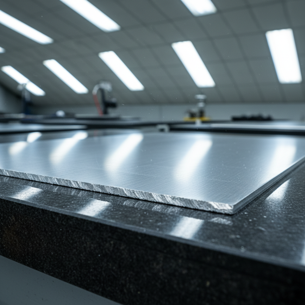
From flat stock to finished shell.
One press. Zero seams.

Drag to compare blank vs. drawn part ← →

Scroll to explore the process
PPAP Level 3Wall Tolerance ±0.02 mmCpk ≥ 1.67Al 3003 · SS 304 · Cu C110In-house CMMEV Battery EnclosuresCompressor HousingsAerospace Sub-tiersZero Seams · Zero WeldsFirst Article in 4 WeeksPPAP Level 3Wall Tolerance ±0.02 mmCpk ≥ 1.67Al 3003 · SS 304 · Cu C110In-house CMMEV Battery EnclosuresCompressor HousingsAerospace Sub-tiersZero Seams · Zero WeldsFirst Article in 4 Weeks
Chapter 01 — Tooling

The die decides
everything.

Every draw starts with clearance math. Punch-to-die clearance is held to 105–115% of material thickness — too tight and you shear, too loose and you wrinkle. We cut our own tooling in-house on a Mazak CNC with ±0.005 mm tolerance.

Punch & Die Cross-SectionLive Animation
Die Aperture Ø62.41.3 mmPUNCHØ60.8 mmBlank positioned
Punch-to-Die Clearance105–115% mat. thickness

Tighter = shear risk. Looser = wrinkling. We hold ±0.005 mm.

Die Radius (Rd)4–8× material thickness

Undersized radius tears. Oversized radius buckles flange.

Blank Holder Force30–50 kN (Al 3003)

Controlled via nitrogen cylinders, monitored every stroke.

÷
Draw Ratio (DR)Max 2.2 first draw

Beyond DR 2.2, earing and fracture risk increases sharply.

Tooling MaterialD2 tool steel, HRC 60–62

Nitrided surface for draw-oil adhesion and wear resistance.

Chapter 02 — Draw Stages

Three passes.
One perfect shell.

Deep drawing isn't one operation — it's a controlled sequence of diameter reductions and wall ironing. Each stage is engineered to stay within the metal's formability envelope.

t=1.18 mmh=38 mm
Diameter
62.4 mm
Wall
1.18 mm
Reduction
DR = 2.1
Stage 1 of 3Cup Drawing

First Draw

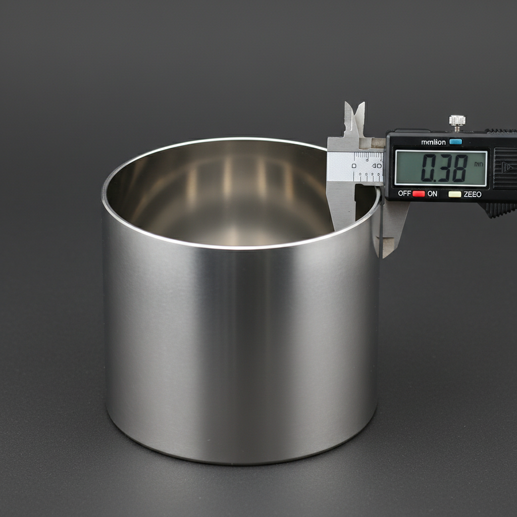
Blank drawn into first cup. Flange wrinkle suppressed by blank holder. Wall thickness drops ~2% from cold work.

Wall Thinning2% reduction
Blank holder force: 38 kN (nitrogen-controlled)
Die radius: 6× material thickness
Draw speed: 180 mm/s
Chapter 03 — Materials

The right alloy
changes everything.

Material selection drives tooling clearance, blank holder force, annealing schedule, and final wall spec. Here's our working comparison for the three alloys we run most.

Metric
3003-H14
304 / 2B
C110 / ETP
Formability
92%
68%
85%
Tensile Strength
150 MPa
515 MPa
220 MPa
Max Draw Ratio
2.2
1.8
2.1
Min Wall Thickness
0.30 mm
0.45 mm
0.35 mm
Best Formability

Aluminum

3003-H14

Best-in-class formability. Excellent corrosion resistance. Preferred for high-volume EV applications where weight matters.

Typical Applications
EV battery enclosures
Capacitor cans
Aerosol cylinders
Formability Index
92/100
Chapter 04 — Quality

PPAP before
the first shipment.

Aerospace sub-tiers and EV Tier-1s don't schedule calls without PPAP Level 3 in hand. We build the documentation package in parallel with tooling — not after. Every dimension gets a control plan entry.

±0.02mm
Wall tolerance held
CMM-verified 100%
Cpk 1.9
Process capability
SPC on every run
PPAPLvl 3
Documentation standard
Full APQP package
Ra 0.4µm
Interior surface finish
Profilometer cert
Control Plan Extract — Drawing Rev. CPPAP Level 3
Code
Characteristic
Tolerance
Class
DIM-01
Wall thickness uniformity
±0.02 mm
Critical
DIM-02
Internal diameter
±0.015 mm
Critical
DIM-03
Shell height / depth
±0.05 mm
Standard
SURF-01
Interior surface finish
Ra ≤ 0.4 µm
Standard
SURF-02
Earing / wrinkling
Zero defects
Critical
MAT-01
Material certification
Cert on file
Standard
PPAP-01
PPAP Level 3 package
Cpk ≥ 1.67
Monitor
PPAP-02
MSA / Gauge R&R
< 10% study var
Standard

Full PPAP package includes: Part Submission Warrant, Dimensional Results, Material Certs, Process Flow, PFMEA, Control Plan, MSA, SPC initial study.

Get Started

Two paths to your
first drawn part.

Free Resource

Deep Draw Design Guide

18-page engineering reference. Wall-thickness-to-diameter ratios, material selection flowchart, tooling clearance tables, and DFM checklist. Used by 400+ procurement engineers.

Fig. 3 — Wall Thickness / Diameter Ratio Chart
Al 3003
92
Cu C110
78
SS 304
55
Fig. 4 — Material Selection Flowchart
Pressure rated?
Weight critical?
Conductivity?

Complete form to unlock

No spam. Engineering content only.

Free Review

Upload Your Part Print for DFM Review

Send us a STEP, DXF, or PDF and our senior tooling engineer will return a DFM report within 2 business days — wall thickness feasibility, recommended draw sequence, and material suggestions.

Drop your part print here

STEP · DXF · PDF — up to 50 MB

DFM Report Includes
Wall thickness feasibility vs. material choice
Recommended draw sequence (1–3 stages)
Tooling cost estimate ± 15%
Lead time projection for first article

2 business day turnaround · No NDA required